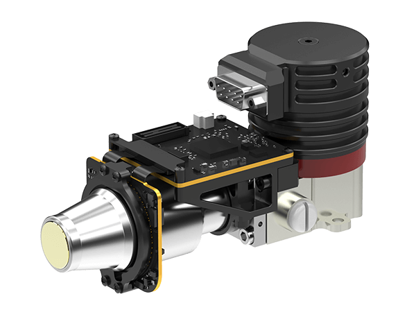
The uncooled infrared focal plane detector can be divided into three major technical parts from design to manufacturing: microbolometer, readout circuit, and vacuum packaging.
1. Microbolometer
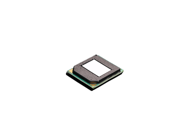
Microbolometer (MB) is a thermistor type sensor element that is compatible with semiconductor processes and can be monolithically integrated with a CMOS readout integrated circuit (ROIC). It is manufactured and processed based on MEMS technology and is composed of a silicon substrate, a bottom reflector, interconnected electrode, thermal insulation pier, thermistor material layer and infrared absorption bridge deck. The currently used thermistor material layers are mainly vanadium oxide (VOx) and amorphous silicon (α-Si) semiconductor thermosensitive film materials.
The infrared absorption bridge deck is composed of pixels with a MEMS micro-bridge structure that are repeatedly arranged in two dimensions on the focal plane. Each pixel (micro-bridge) measures the thermal radiation at a specific incident angle. The microbridge is composed of multiple layers of materials. From top to bottom, they are an infrared absorbing layer, a heat-sensitive layer, and bridge arms and piers that serve as support and electrical connections. The bridge arms and piers are connected to the silicon substrate through COMS system connected. When the bridge deck absorbs external infrared radiation, the microbridge absorption layer absorbs infrared energy and produces subtle temperature changes respectively, causing corresponding changes in the resistance value of the thermosensitive layer of each microbridge. ROIC amplifies the microbridge resistance changes through interconnected electrodes and converts them into electrical video signal output.
2. Readout circuit (ROIC)
The readout circuit of the uncooled infrared focal plane detector outputs the tiny resistance changes of each microbolometer as an electrical signal. The signal current generated by the infrared radiation irradiated on the focal plane is very small, generally in the nanoampere or even picoamp level. This small signal is easily interfered by other noise, so the electrical noise of the readout circuit must be controlled as small as possible in order to avoid unnecessary impact on the sensitivity index of the detector.
The working principle of the traditional readout circuit is: apply a fixed low-noise bias voltage to the heat-sensitive film of the microbolometer, obtain its resistance change with temperature in the form of current change, and then convert it into a voltage by an integrator signal, output through the driver.
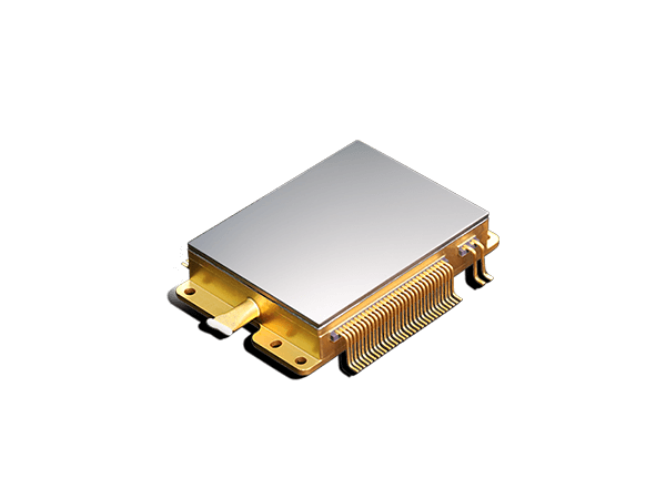
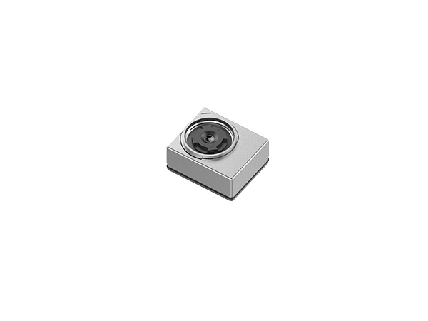
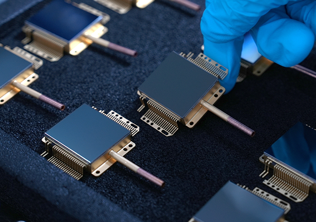
3. Vacuum packaging technology
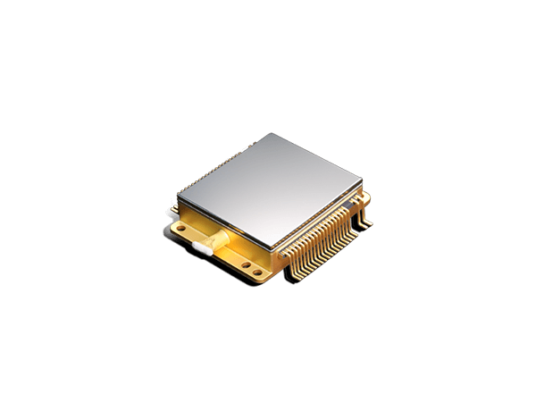
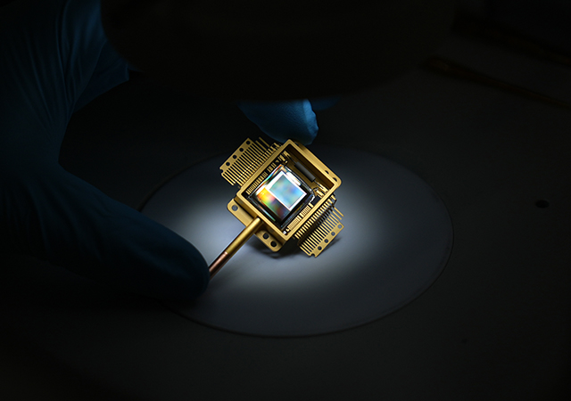
The temperature change after the microbolometer receives the target infrared radiation is very weak. In order to maintain the heat on it and avoid heat exchange with air molecules, it needs to be placed in a vacuum environment to work. Generally, the vacuum degree is required less than 0.01mbar (ie 0.00001atm). The requirements for vacuum packaging of uncooled infrared focal plane detectors are: excellent and reliable sealing; infrared window with high transmittance; high yield; low cost. Current packaging technology can be divided into chip level, wafer level, pixel level, etc.
Go Top